
In Class IX, we learned that a force, when applied on a rigid body, can cause only motion in it. However, when applied on a non-rigid body, it can cause both a change in its size or shape and motion.
Mathematical Definition: Force is the rate of change of linear momentum.
$$ \vec{F} = \frac{d\vec{p}}{dt} = \frac{d(m\vec{v})}{dt} = m\vec{a} $$Units:
A rigid body, when acted upon by a force, can undergo two types of motion:
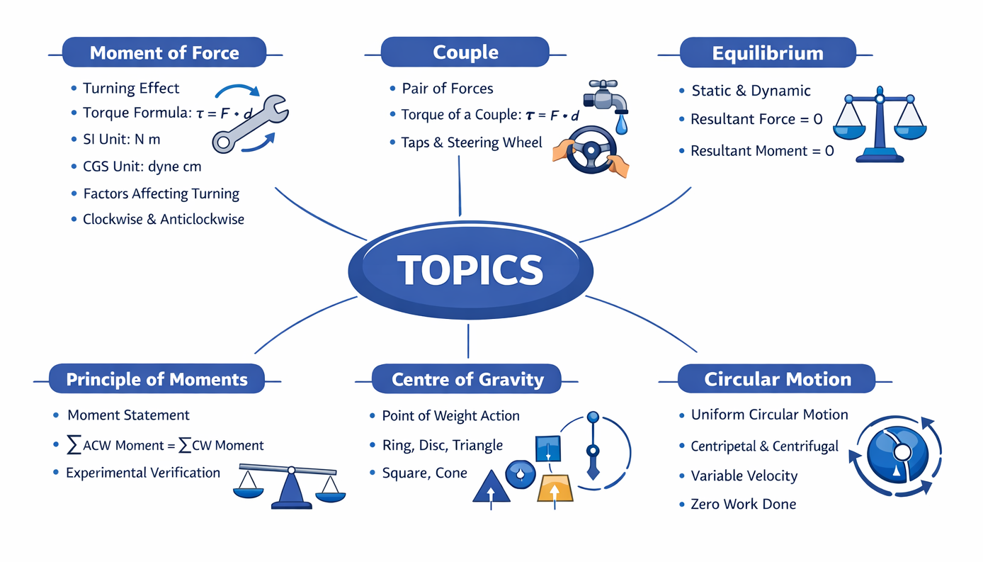
When a force acts on a stationary rigid body which is free to move, the body starts moving in a straight path in the direction of the force.
Translational motion of a ball on pushing.
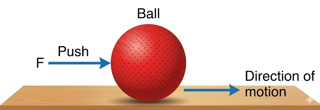
If the body is pivoted at a point and the force is applied at a suitable point, it rotates the body about the axis passing through the pivoted point. This turning effect is called rotational motion.
Rotational motion of a wheel pivoted at its centre.
Self-Check: State one way to change the direction of rotation of a body.
Ans: By changing the point of application of the force, or by changing the direction of the force applied.
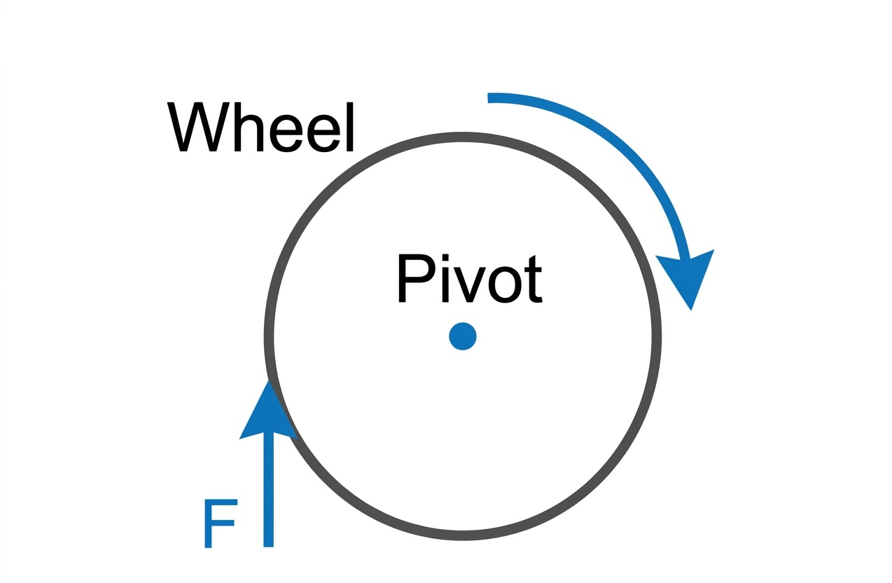
The turning effect of a force on a body about an axis is called the Moment of Force or Torque.
Moment of a force about a pivoted point.
Consider a body pivoted at point O. If a force $F$ is applied horizontally on the body at point P, the force is unable to produce linear motion because the body is not free to move. Instead, this force turns the body about the vertical axis passing through O.
Unit: Newton-metre (N m)
The turning effect on a body by a force depends on the following two factors:
A body is pivoted at a point. A force of 10 N is applied at a distance of 30 cm from the pivot. Calculate the moment of force about the pivot.
Solution: $F = 10 \text{ N}$, $r = 30 \text{ cm} = 0.3 \text{ m}$
$\text{Moment of force} = F \times r = 10 \text{ N} \times 0.3 \text{ m} = \mathbf{3 \text{ N m}}$
The moment of a force of 5 N about a point P is 2 N m. Calculate the distance of line of action of the force from the point P.
Solution: $\text{Moment} = 2 \text{ N m}$, $F = 5 \text{ N}$
$\text{Moment} = F \times d \implies 2 = 5 \times d \implies d = \mathbf{0.4 \text{ m}}$
To produce maximum turning effect with minimum force, the force should be applied at a point where the perpendicular distance from the axis is maximum.
Unit of moment of force = Unit of force $\times$ Unit of distance.
Relationship: $1 \text{ N m} = 10^5 \text{ dyne} \times 10^2 \text{ cm} = 10^7 \text{ dyne cm}$
Gravitational Units: kgf m and gf cm. ($1 \text{ kgf m} \approx 9.8 \text{ N m}$).
The moment of force is a vector quantity. Its direction is along the axis of rotation, either outwards or inwards.
Concept Check (MCQ): The moment of a force about a given axis depends:
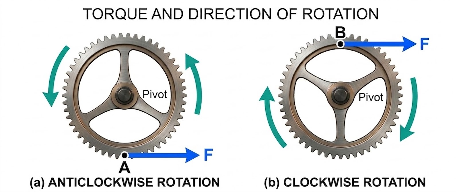
Answer: (d)Conventionally, if the effect on the body is to turn it anticlockwise, the moment of force is called the anticlockwise moment and it is taken as positive (+).
If the effect is to turn it clockwise, the moment of force is called the clockwise moment and it is taken as negative (-).
 and Clockwise (-).jpg)
Sign convention for moments: Anticlockwise (+) and Clockwise (-).
A force $F$ is applied normal to the door at its handle $P$, which is provided at the maximum distance from the hinges. This ensures a larger moment of force to open the door with minimum effort.
Q. Why is it easier to open a door by applying the force at the free end of it?
Ans: By applying force at the free end, the perpendicular distance from the hinges (axis of rotation) is maximum. This produces a larger moment of force (torque) with less effort.
The iron door of a building is 3 m broad. It can be opened by applying a force of 100 N normally at the middle of the door. Calculate: (a) the torque needed to open the door, (b) the least force and its point of application to open the door.
Solution:
(a) Force applied at middle ($r = 1.5 \text{ m}$): $\text{Torque} = 100 \times 1.5 = \mathbf{150 \text{ N m}}$
(b) Least force is applied at the free end ($r' = 3 \text{ m}$): $F' \times 3 = 150 \implies F' = \mathbf{50 \text{ N}}$
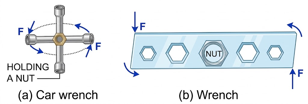
To turn a steering wheel, a force is applied tangentially on the rim of the wheel. The sense of rotation is changed by changing the point of application of force.
Changing the sense of rotation by changing the point of application of force.
Q. It is easier to turn the steering wheel of a large diameter than that of a small diameter. Give reason.
Ans: A larger diameter provides a larger perpendicular distance (couple arm) for the applied forces, resulting in a greater turning effect for the same amount of force.
In a bicycle, a small force is applied on the foot pedal of a toothed wheel bigger than the rear wheel to produce a large moment of force.
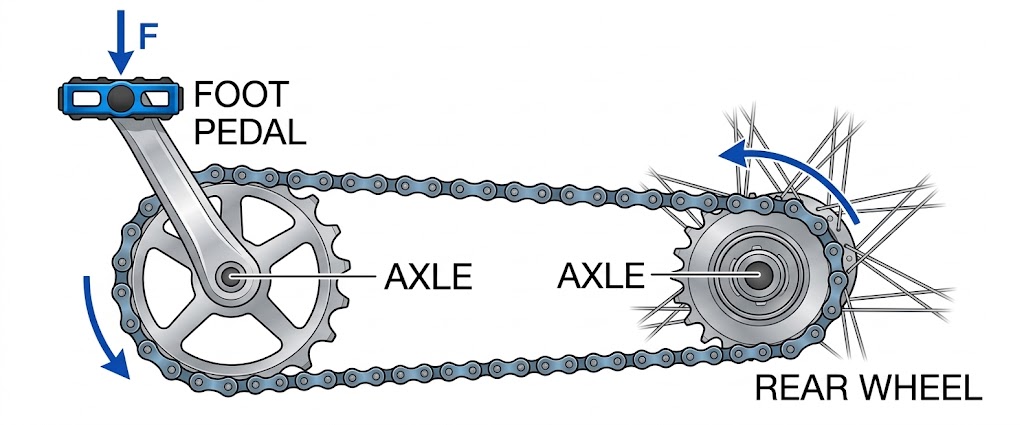
Mechanism of a bicycle pedal and rear wheel.
A spanner used to tighten or loosen a nut has a long handle to produce a large moment of force by a small force applied at its end.
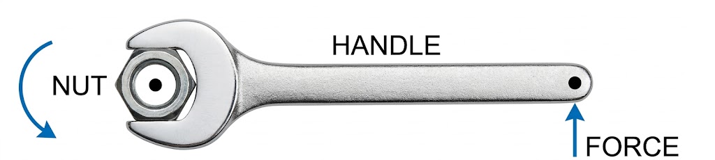
Using tools with long handles to increase torque.
Q. A spanner (or wrench) has a long handle. Why?
Ans: A long handle increases the perpendicular distance from the axis of rotation, allowing a small force to produce the large torque required to loosen or tighten a nut.
A mechanic can open a nut by applying a force of 150 N while using a lever handle of length 40 cm. How long handle is required if he wants to open it by applying a force of only 50 N?
Solution:
Moment required = $150 \text{ N} \times 0.4 \text{ m} = 60 \text{ N m}$
New Force $F' = 50 \text{ N}$. Let new length be $L$.
$50 \text{ N} \times L = 60 \text{ N m} \implies L = \mathbf{1.2 \text{ m}}$
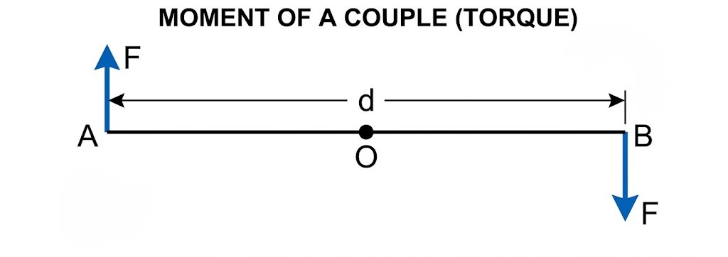
A single force applied on a pivoted body alone does not cause rotation. In reality, rotation is always produced by a pair of forces. When we open a door, two forces act: (i) the force we exert at the handle, and (ii) an equal and opposite force of reaction at the hinge.
Definition: Two equal and opposite parallel forces, not acting along the same line, form a couple.
Effect: A couple produces pure rotational motion about a point.
Moment of a couple acting on a rigid bar.
Concept Check (MCQ): A body is acted upon by two unequal forces in opposite directions, but not in the same line. The effect is that:
Answer: (d)The perpendicular distance between the two forces is called the couple arm.
 produces rotation Water tap, Tightening a cap, Turning a key, and Steering wheel..jpg)
Everyday examples where a pair of forces (couple) produces rotation: Water tap, Tightening a cap, Turning a key, and Steering wheel.
When a number of forces acting on a body produce no change in its state of rest or of linear or rotational motion, the body is said to be in equilibrium.
When a body remains at rest under the influence of several forces, it is in static equilibrium.
Example: A book lying on a table. The weight of the book is balanced by the normal reaction from the table.
Static equilibrium: Resultant force and moment are zero.

A wheel of diameter 2 m is kept stationary under the action of (i) a horizontal force $F_1$ at A and (ii) a vertical force $F_2$ at B. Find the ratio between $F_1$ and $F_2$. Given $AO = 2.5 \text{ cm}$ and $BO' = 1.5 \text{ cm}$.
Solution: For equilibrium, Clockwise moment = Anticlockwise moment.
$F_1 \times OA = F_2 \times OO' \implies F_1 \times 2.5 = F_2 \times 2.0 \implies \frac{F_1}{F_2} = \frac{20}{25} = \mathbf{4:5}$
When a body remains in the same state of motion (translational or rotational) under the influence of several forces, it is in dynamic equilibrium.
Examples:
For a body to be in equilibrium, the following two conditions must be satisfied:
$\implies \sum \text{Anticlockwise Moments} = \sum \text{Clockwise Moments}$
According to the principle of moments, if a body is in equilibrium under the action of several forces, the algebraic sum of the moments of all the forces about the pivoted point is zero.
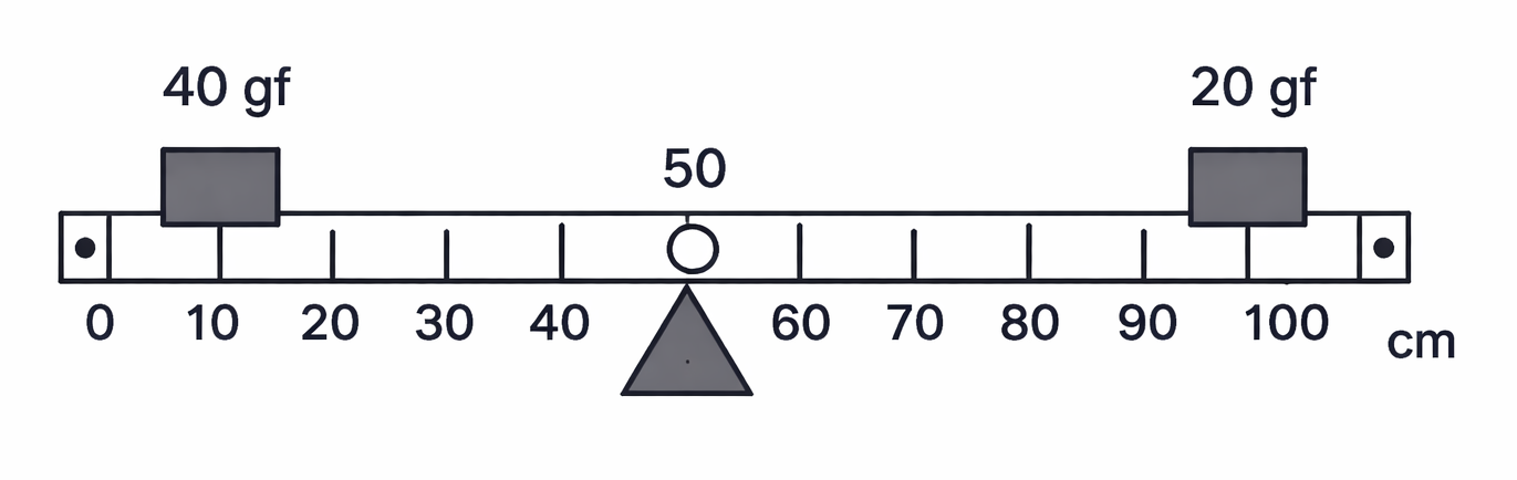
Suspend a metre rule horizontally from a fixed support by means of a strong thread at O (the 50 cm mark). Suspend two spring balances A and B on either side with weights $W_1$ and $W_2$ at distances $l_1$ and $l_2$ respectively.
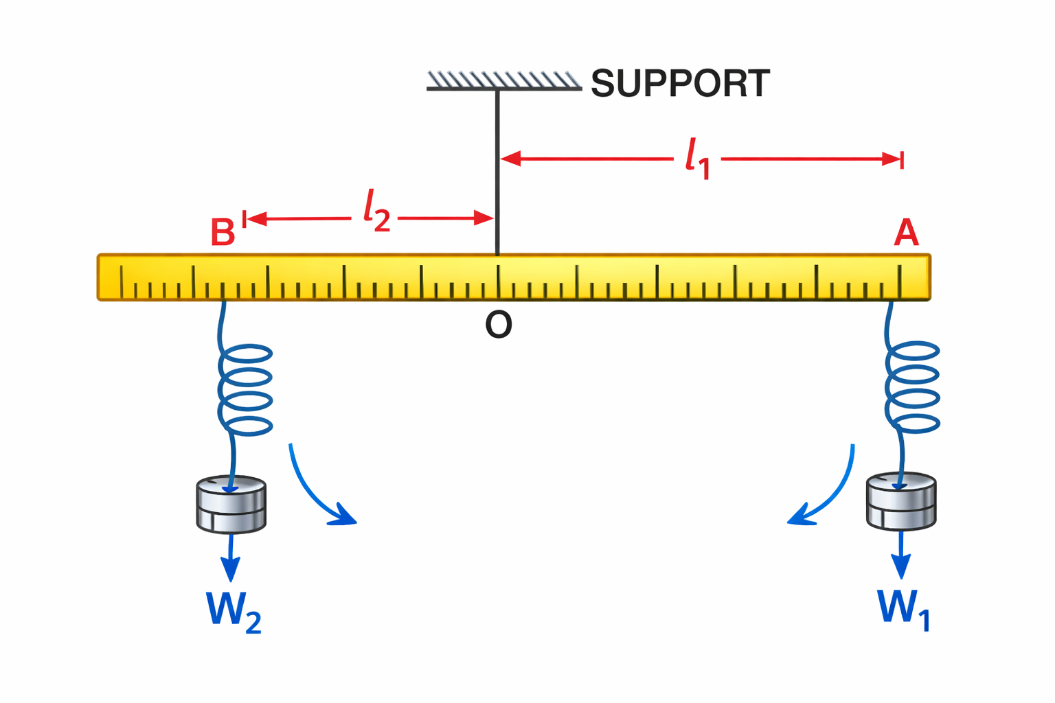
Experimental verification: $W_1 \times l_1 = W_2 \times l_2$.
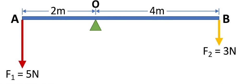
The diagram shows two forces $F_1 = 5 \text{ N}$ and $F_2 = 3 \text{ N}$ acting at points A and B of a rod pivoted at a point O, such that $OA = 2 \text{ m}$ and $OB = 4 \text{ m}$. Calculate: (i) Moment of force $F_1$ about O, (ii) Moment of force $F_2$ about O, (iii) Total moment of forces about O.
Ans: (i) $10 \text{ N m}$ (Anticlockwise), (ii) $12 \text{ N m}$ (Clockwise), (iii) $2 \text{ N m}$ (Clockwise)
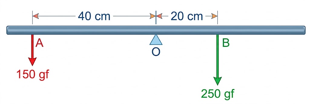
A uniform metre rule weighing $100 \text{ gf}$ is pivoted at its centre O. Two weights $150 \text{ gf}$ and $250 \text{ gf}$ hang from points A and B of the metre rule such that $OA = 40 \text{ cm}$ and $OB = 20 \text{ cm}$. Calculate: (i) total anticlockwise moment, (ii) total clockwise moment, (iii) the distance from O where a $100 \text{ gf}$ weight should be placed to balance the rule.
Ans: (i) $6000 \text{ gf cm}$, (ii) $5000 \text{ gf cm}$, (iii) $10 \text{ cm}$ on the right side of O.
A uniform metre rule of mass $100 \text{ g}$ is balanced on a fulcrum at $40 \text{ cm}$ by suspending an unknown mass $m$ at the mark $20 \text{ cm}$. Calculate: (i) the value of $m$, (ii) if the mass $m$ is moved to $10 \text{ cm}$, where should another mass of $50 \text{ g}$ be placed to keep it balanced?
Ans: (i) $m = 50 \text{ g}$, (ii) At the $50 \text{ cm}$ mark.
A boy weighing $20 \text{ kgf}$ sits at one end of a $4 \text{ m}$ long see-saw, which gets depressed at this end. How can it be brought to the horizontal position by a man weighing $40 \text{ kgf}$?
Ans: By the man sitting at a distance of $1 \text{ m}$ from the centre on the side opposite to the boy.
The Centre of Gravity of a body is the point about which the algebraic sum of moments of weights of all the particles constituting the body is zero. The entire weight of the body can be considered to act at this point.
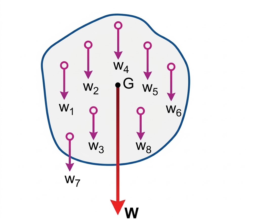
The algebraic sum of moments of weights about G is zero.
Note: (1) The position of C.G. depends on the shape (mass distribution). It changes if the body is deformed.
(2) It is not necessary for the C.G. to be within the material of the body. For example, the C.G. of a ring lies at its geometric centre, where there is no material.
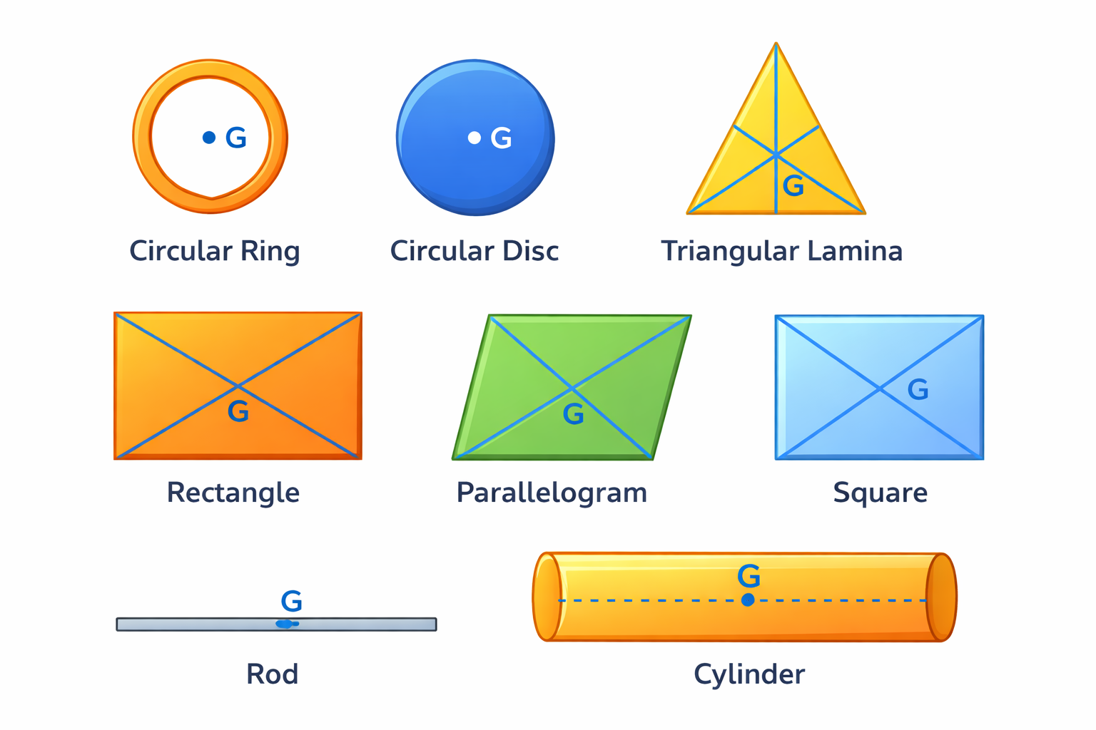
Centre of gravity of some regular objects.
A solid body can be balanced by supporting it at its centre of gravity. For example, a uniform metre rule has its C.G. at the 50 cm mark. It can be balanced on a knife edge (or finger tip) by keeping it exactly below the 50 cm mark.
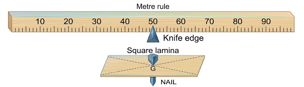
Bodies balanced at their centre of gravity.
The C.G. of an irregular lamina can be determined by the method of balance using a plumb line. If a body is freely suspended from a point, it comes to rest in a position where its C.G. lies vertically below the point of suspension.
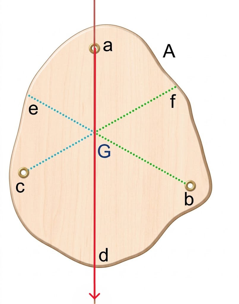
Finding C.G. of an irregular lamina using a plumb line.
Q1. Can centre of gravity of a body be situated outside its material? Give an example.
Ans: Yes. For example, the C.G. of a uniform ring or a hollow sphere lies at its geometric centre, where there is no material.
Q2. State factors on which the position of centre of gravity of a body depends.
Ans: It depends on the shape of the body (i.e., the distribution of mass of particles in it). It changes if the body is deformed.
MCQ 1. The centre of gravity of a uniform ball is:
Answer: (a)MCQ 2. The centre of gravity of a hollow cone of height $h$ is at distance $x$ from its vertex where the value of $x$ is:
Answer: (c)Q3. A square cardboard is suspended by passing a pin through a narrow hole at its one corner. Draw a diagram to show its rest position.
Ans: In the rest position, the centre of gravity G must lie vertically below the point of suspension S.
Q4. State whether true or false:
Self-Check: Does the Centre of Gravity of a body always lie within its material?
Ans: No. For example, the C.G. of a hollow sphere or a ring lies at its geometric centre, where there is no material.
A physical balance has its arms of length $60 \text{ cm}$ and $40 \text{ cm}$. What weight kept on the pan of the longer arm will balance an object of weight $100 \text{ gf}$ kept on the other pan?
Ans: $66.67 \text{ gf}$
Definition: When a particle moves with a constant speed in a circular path, its motion is called Uniform Circular Motion.
Important: Velocity is variable (direction changes), so it is an accelerated motion.
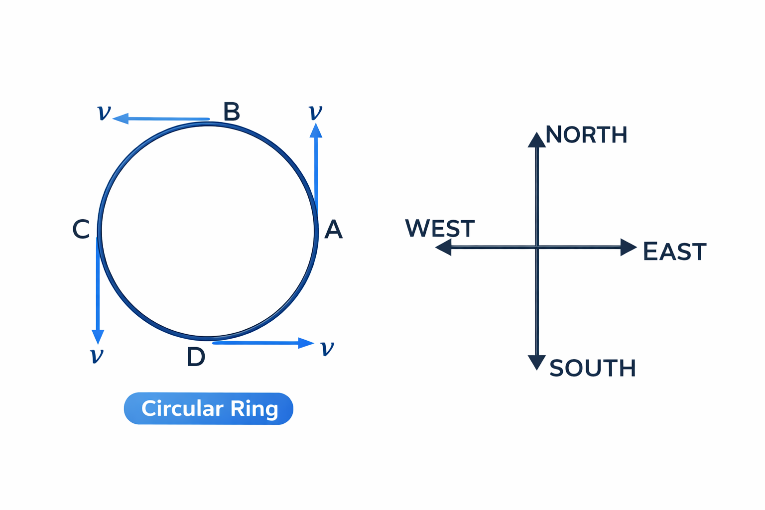
Direction of velocity at different points in uniform circular motion.
Note: At any point, the direction of motion is along the tangent drawn at that point. Thus, velocity is variable even if speed is uniform.
| Uniform Linear Motion | Uniform Circular Motion |
|---|---|
| Speed and velocity are both constant. | Speed is constant, but velocity is variable. |
| Acceleration is zero (unaccelerated). | Acceleration is non-zero (accelerated). |
A force required to change the direction of motion of a particle in a circular path is called Centripetal Force. It is always directed towards the centre of the circle.
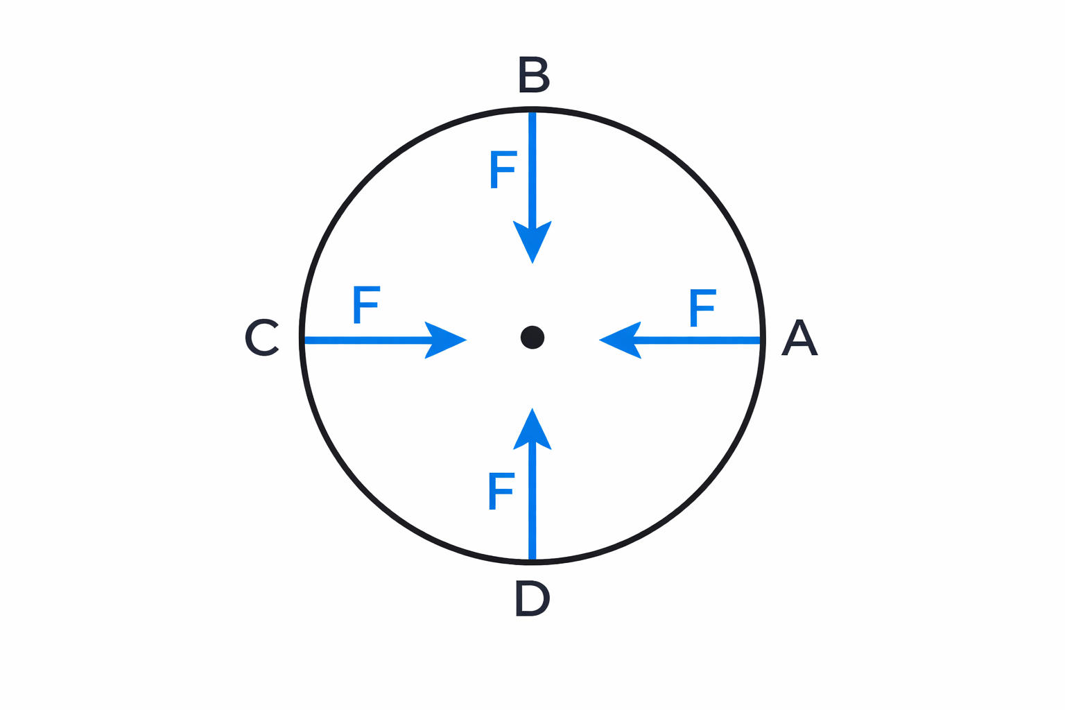
Centripetal force is always "centre-seeking".
Examples of Centripetal Force:
A fictitious force assumed by an observer moving in a circular path, acting in a direction opposite to centrifugal force (away from the centre), is called Centrifugal Force. Its magnitude is equal to the centripetal force.
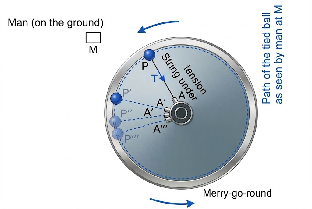
Fig. 1.44: Merry-go-round observations
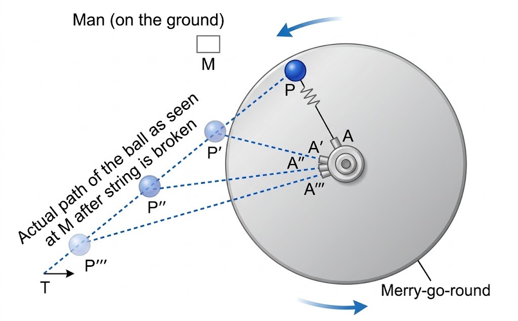
Fig. 1.45: Centrifugal force direction
Centrifugal force: A fictitious force observed in rotating frames.
Centrifugal force is not a real force; it is not the force of reaction of the centripetal force. It is a fictitious force assumed to explain observations in a rotating frame.
Q1. Differentiate between a uniform linear motion and a uniform circular motion.
Ans: In uniform linear motion, velocity is constant and acceleration is zero. In uniform circular motion, velocity is variable (due to change in direction) and motion is accelerated.
Q2. Is it possible to have an accelerated motion with a constant speed? Name such motion.
Ans: Yes, Uniform Circular Motion is an accelerated motion with constant speed because the direction of velocity changes continuously.
MCQ 1. Which of the following quantities remains constant in a uniform circular motion:
Answer: (b)MCQ 2. The centrifugal force is:
Answer: (c)Q3. A stone tied at the end of a thread is whirled in a horizontal circle with uniform speed.
Work done in uniform circular motion is zero because the force is always perpendicular to the displacement ($\cos 90^\circ = 0$).
Q4. State two differences between Centripetal and Centrifugal force.
Ans: (1) Centripetal force is a real force, while centrifugal force is a fictitious force. (2) Centripetal force is directed towards the centre, while centrifugal force is directed away from the centre.
Q5. Is centrifugal force a real force?
Ans: No, it is a fictitious (or virtual) force assumed by an observer in a rotating frame.
Q6. Observations on a Rotating Disc (Merry-go-round):
If a pebble is placed on a rotating disc:
Q7. State whether true or false: